Dynamips / Dynagen Tutorial
Documentation Revision 1.10.2
Configuring your Telnet Client
Working with the Management Console
Communicating with Real Networks
Client / Server and Multi-server Operation
· How do I determine idle pc values from Dynagen?
· http://dynagen.org/tutorial.htm#_Toc165530762
Introduction
Dynamips is a Cisco router emulator written by Christophe Fillot. It emulates 2691, 3620, 3640, 3660, 3725, 3745, and 7206 hardware platforms, and runs standard IOS images. In Chris’ own words:
This kind of emulator would be useful to:
· Be used as a training platform, with software used in real world. It would allow people to become more familiar with Cisco devices, Cisco being the world leader in networking technologies ;
· Test and experiment features of Cisco IOS ;
· Check quickly configurations to be deployed later on real routers.
Of course, this emulator cannot replace a real router, it is simply a complementary tool to real labs for administrators of Cisco networks or people wanting to pass their CCNA/CCNP/CCIE exams.
Dynagen is a text-based front end for Dynamips, which uses the “Hypervisor” mode for communication with Dynamips. Dynagen simplifies building and working with virtual networks:
- Uses a simple, easy to understand configuration file for specifying virtual router hardware configurations
- Simple syntax for interconnecting routers, bridges, frame-relay and ATM, and Ethernet switches. No need to deal with NetIOs
- Can work in a client / server mode, with Dynagen running on your workstation communicating with Dynamips running on a back-end server. Dynagen can also control multiple Dynamips servers simultaneously for distributing large virtual networks across several machines. Or you can run Dynamips and Dyngen on the same system
- Provides a management CLI for listing devices, starting, stopping, reloading, suspending, resuming, and connecting to the consoles of virtual routers.
Dynagen is written in Python, and is therefore compatible with any platform for which there is a Python interpreter (which is to say, many). The design is modular, with a separate OOP API for interfacing with Dynamips. Other Python applications could be written that use this API for programmatically provisioning virtual networks, or to provide other front-ends. Yannick Le Teigner is working on Dynagui; a GUI front-end using this library.
If somehow you have stumbled upon this tutorial without first finding the Dynamips or Dynagen web sites, here they are along with some other important links:
Dynamips (the actual emulator): http://www.ipflow.utc.fr/index.php/Cisco_7200_Simulator
Dynamips Blog (where most of the action is): http://www.ipflow.utc.fr/blog/
Dynagen (a front-end to the emulator): http://dyna-gen.sourceforge.net/
Dynagui: http://dynagui.sourceforge.net/
Dynamips / Dynagen Bug tracking: http://www.ipflow.utc.fr/bts/
Hacki’s Dynamips / Dynagen / Dynagui Forum: http://hacki.at/7200emu/index.php
Special thanks to the creators of the ConfigObj library at http://www.voidspace.org.uk/python/modules.shtml#configobj. This library is used by Dynagen for reading its configuration files.
Installing
Dynagen runs on any platform that supports Python, which is to say nearly any platform. I have also put together a Windows installer package that includes Dynamips and provides a compiled version of Dynagen, eliminating the need to install Python. It also provides Explorer “integration” so you can double-click on network files in order to run them.
First, install libpcap, or winpcap depending on your platform on the machine on which you intend to run Dynamips. This is used to provide bridging router interfaces to physical network cards. Windows users will need to install Winpcap 4.0 or later, which is current in beta.
Then, Windows users should install the Windows installer package. This provides everything you need to run Dynamips / Dynagen on local or remote machines.
Linux users should download the Dynamips / Dynagen tarball, and extract it to a suitable location (e.g. /opt/dynagen). Then create symlinks to the Dynagen and Dynamips executables in /usr/local/bin, or somewhere else in your PATH.
Note: If you are running Dynamips on a RedHat or Fedora system, take a look at Dynamips FAQ item #2 if you are experiencing segfaults when you try to run Dynamips.
IOS Images
Dynamips runs real Cisco 2691, 3620, 3640, 3660, 3725, 3745, and 7200 IOS images. From the Dynamips FAQ:
Can you provide a Cisco IOS image for a 7200
to me?
No, I am not allowed to distribute any IOS image. You will have to find one by yourself, this should not be a problem if you are a Cisco customer.
On Windows, drop the image in C:\Program Files\Dynamips\images. You can actually drop the images anywhere you want, but the sample labs are configured to look here. On Linux/Unix systems, designate a location to store your images and drop them there (I like to use /opt/images, but it’s your system.)
Cisco IOS images are compressed. These compressed images will work just fine with Dynamips, however the boot process is slowed significantly by this decompression process (just like on real routers). It is recommended that you decompress the images beforehand, so the emulator doesn’t have to. You can do this with the “unzip” utility on Linux/Unix/Cygwin as follows:
unzip -p c7200-g6ik8s-mz.124-2.T1.bin >
c7200-g6ik8s-mz.124-2.T1.image
You will receive a warning from unzip, which you can safely ignore.
Resource Utilization
Dynamips uses a fair amount of RAM and CPU in order to accomplish its emulation magic. If you intend to run an IOS image that requires 256 MB of RAM on a real 7200 router, and you devote 256 MB of RAM to your virtual router instance, it will allocate 256 MB of working set memory. Dynamips also allocates (by default) 64 MB of RAM / instance on Unix systems (16 MB on Windows systems) to cache JIT translations. This will be the total working set size; by default the amount of your system’s actual RAM used will typically be significantly less. This is because by default Dynamips uses memory mapped files for the routers’ virtual memory. In the working directory you will see temporary “ram” files equal to the size of the virtual routers’ RAM size. Your OS will naturally cache in RAM the sections of the mmap files that are being used. (See the Memory Usage Optimizations section for configuration options that can signficanly reduce memory utilization).
If you have plenty RAM, and you know what you are doing, set “mmap = false” in the device default or router sections of your labs to disable mmap for those instances.
Dynamips also uses a lot of CPU, because it is emulating a router’s CPU instruction-by-instruction. it initially has no way of knowing when the virtual router’s CPU is idle so it dutifully executes all the instructions that make up IOS’s idle routines just as it would execute the instructions that perform “real” work. But once you have run through the “Idle-PC” process for a given IOS image, CPU utilization decreases drastically. More on this later.
Configuring your Telnet Client
Dynagen includes a console command that allows you to connect to the virtual router consoles directly from the CLI. But you must first configure the dynagen.ini file (located in C:\Program Files\Dynagen on Windows systems, or wherever you extracted the tarball on Unix systems) to tell it which telnet client to use. Uncomment the line appropriate for your system, or craft your own to use your favorite telnet client. See the comments in the ini file for instructions.
Network Files
Dynagen uses a single “network file” to store the configuration of all the routers, switches, and interconnections that make up a virtual lab. This file uses a simple INI file-like syntax. Open up the simple1.net file in a text editor (on Windows there is a shortcut to the “Dynagen Sample Labs” directory on the desktop).
# Simple lab
Any line prefaced with a # is a comment, and is ignored
[localhost]
The first section specifies the host that is running Dynamips. In this case, we intend to run Dynamips on the same machine as Dynagen, so we specify localhost. If Dynamips were running on a different machine, you would put the hostname or IP address of that machine here instead (we’ll see an example of that a bit later on.)
[[7200]]
The next section is indented, and double bracketed. This means that what follows is configuration that applies to the Dynamips server specified in the section above (in this case, localhost). All whitespace is actually ignored, so the indentation is just for looks. The double-bracket is what really means that this section is nested under the [localhost] section.
This [[7200]] section defines all the defaults that will be applied to any 7200 router instance we create. This makes things easy, by allowing us to specify common things like RAM size and IOS image only once. Note that you can specify defaults, and later override them in specific router instance definitions.
image = \Program Files\Dynamips\images\c7200-jk9o3s-mz.124-7a.image
# On Linux / Unix use forward slashes:
# image = /opt/7200-images/c7200-jk9o3s-mz.124-7a.image
The image keyword specifies the location on the system running Dynamips (in this example our local machine) of the image we want to use by default for all router instances. Here we are pointing to a 12.4 image on a Windows system. For Linux/Unix systems, use forward slashes instead, as shown in the comment.
npe = npe-400
ram = 160
Each of our router instances is going use an NPE-400, and be allocated 160 MB of RAM .
[[ROUTER R1]]
Now, we are defining a virtual router instance with the ROUTER keyword. The string following this keyword is the name we are assigning to this router, in this case “R1”. This name is just the name that is used by Dynamips / Dynagen. It has nothing to do with the hostname that you assign in IOS to the router (although it will probably be less confusing if you just keep them the same.)
s1/0 = R2 s1/0
This line states that we are going to take R1’s Serial 1/0 interface, and connect it to R2’s Serial 1/0 interface (via virtual back-to-back serial cable). Dynagen automatically “installs” a PA-8T adapter in Port 1 to accommodate this connection on both R1 and R2 (note there is a way to override this behavior if, for example, you wanted to use a PA-4T+ instead for some reason).
[[router R2]]
Now we create a 2nd router, creatively name R2. This is the same R2 that is referenced in the line above that connects R1 and R2’s serial interfaces. As you can see, the ROUTER keyword is not case significant. (None of the keywords are.)
# No need to specify an adapter here, it is taken care of
# by the interface specification under Router R1
Although we have to create the R2 router, we do not need to specify any adapters here. R2’s Serial 1/0 interface was already created back when we connected it to R1’s Serial 1/0 above.
Running Simple Lab #1
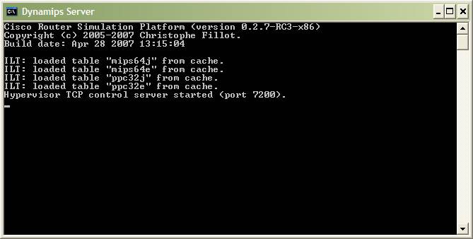
In order to run this virtual lab, first start up the Dynamips server on your local machine. If you used the Windows installer, you will find a shortcut on the desktop titled “Dynamips Server”. Running this starts up the server (listening on port 7200 by default) in a window like this:
On Linux / Mac / Unix, start up the server in the background. For example:
dynamips –H 7200 &
On Windows, open the simple1.net file in explorer and Dynagen is automatically launched and the network started:
On Linux / Unix, either associate “.net” files with dyangen in whatever file manager you use, or run it from the command line:
dynagen simple1.net
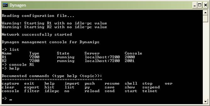
For now, ignore the “no idle-pc value” warning; we’ll get to this a bit later. To see all the devices in this virtual lab, use the list command:
This tells us that there are two routers, R1 & R2. They are both currently running on the local host. R1’s console port is tied to TCP port 2000, and R2’s to port 2001. Telnet to these ports to connect to the virtual router instances. Or, if you configured the dynagen.ini file to specify your telnet client, just type “console R1” to connect to R1’s console.
Even better, you can type “console /all” and a console window will appear for each of your virtual routers. If you use Linux, OS X, or Tera Term SSH on Windows “console /all” works well because the title bar include the name of the router. However the Windows telnet command included with the OS does not seem to allow this. (If anyone can come up with a work-around for this please let me know. I’ve tried setting the title using the “start” command, and it is overwritten as soon as telnet is launched.). But Dynamips lets you know which router you are connecting to as its first line of output inside the telnet window, so you can identify it that way. By the way, the “console” command can be abbreviated as “con” – e.g. “con /all”.
Assign appropriate IP addresses to the Serial 1/0 interfaces on both routers, and “no shut” them, and you should find that they are indeed connected.
Working with the Management Console
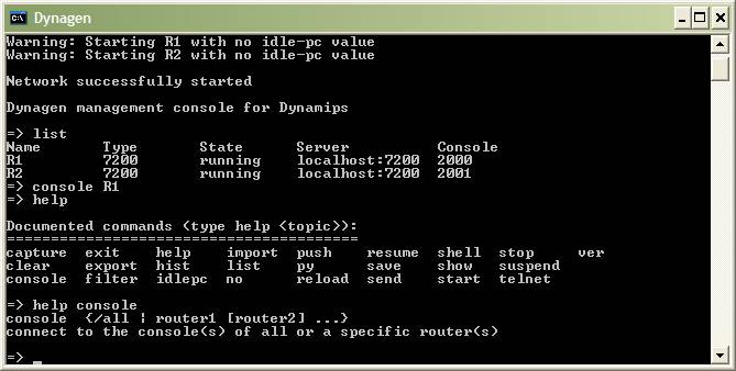
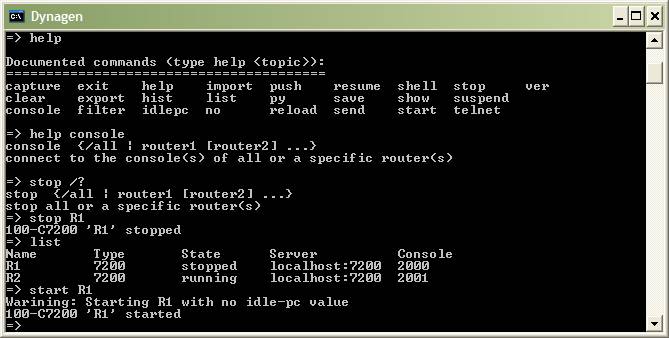
From the Management Console, use the help command to see a list of valid commands:
To get help on a particular command, either type help command or command ?. For example:
On platforms that provide the Readline library (Linux/Unix) the console will have tab completion. (I have not yet found a suitable Python Readline library for Windows to provide this functionality. If anyone can find one that *they have tested with Dynagen and works* please let me know.)
To “power off” a virtual router, use the stop command. Help shows the syntax as:
stop {/all | router1 [router2] ...}
To shut down a single router, type use stop routername:
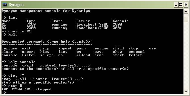
And sure enough, the router is now stopped:
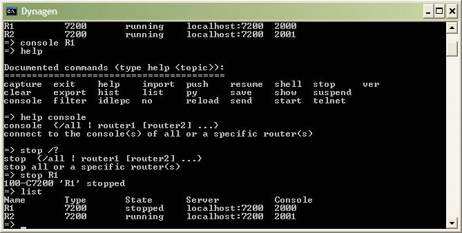
You can also provide a list of routers to stop, or issue as stop /all to shut down all router instances.
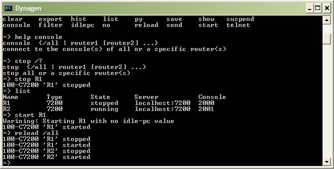
To restart R1, use start command:
start {/all | router1 [router2] ...}
The IOS reload command is not suppored by dynamips in virtual routers. So you can use the Dynagen reload command. It performs a stop, followed by a start. To reload all routers in the entire lab, issue a reload /all:
The suspend and resume commands have a similar syntax as stop and start, but they temporarily pause the specified routers:
The exit command stops and deletes all devices from the network, and exits dynagen. If you exit the Management Console, your simulation will no longer be running.
Calculating Idle-PC values
You may have noticed that the previous lab caused your system’s CPU to peg at 100% and stay there. This is because Dynamips does not know when the virtual router is idle and when it is performing useful work. The “idlepc” command performs analysis on a running image to determine the most likely points in the code that represent an idle loop in IOS. Once applied, Dynamips “sleeps” the virtual router occasionally when this idle loop is executed significantly reducing CPU consumption on the host without reducing the virtual router’s capacity to perform real work.
Here is how the process is performed. First, open a lab and make sure only one router instance is running (stop any others in the lab if need be):
Then, telnet to the running router instance. If you are presented with IOS autoconfig prompt, respond with “no”. Otherwise, do not press anything:
Wait for all the interfaces to initialize, then wait a bit to ensure that the router is no longer booting and is idle. Your session should look something like this:
Now, switch back to the Dynagen management console, and issue an “idlepc get routername”. You will see a message that statistics are being gathered, and about 10 seconds later you should see a list of potential idlepc values:
Values that will most likely provide better results are marked with an asterisk. Select one of the values to try from the menu and press Enter. You should notice your host (the one running the dynamips process) CPU utilization drop dramatically. If so, you’ve found a good idlepc value for this particular IOS image.
If your CPU usage did not drop, it’s time to try a different value. Type “idlepc show routername” to show the list of values determined earlier again, and this time select a different one.
The new idlepc value will take effect dynamically. Once you’ve found a value that works, you can save it to your local idlepc database with “idlepc save routername db”. This stores the idlepc value for this IOS image in the file specified in dynagen.ini with the “idledb” option. The default is a file name “dynagenidledb.ini” in your $HOME or “Documents and Settings” folder (depending on your platform).
Once an idlepc value is in the database, it will be automatically applied whenever a router in one of your labs uses this image. If Dyagen starts a router without being able to find an idlepc value, it gives the “Warning: Starting xxx with no idle-pc value” message. If you would prefer to store the idlepc value directly in your network file, use “idlepc save routername” to add an “idlepc = xxxx” line to the router definition section (e.g. “[[ROUTER R1]]”) or use “idlepc save rotuername default” to store it in the default section of your network file for that router platform (e.g. “[[7200]]”).
A few words on Idle-PC values. They are particular to an IOS image. They will be different for different IOS versions, and even for different feature-sets of the same IOS version. However Idle-PC values are not particular to your host PC, operating system, or to the version of dynamips. So “dynagenidledb.ini” files from one system can be freely copied, merged, shared with others, etc.
The idlepc database is indexed by the name of your IOS image as specified in the “image =” line of your network file (minus the directories). So all your images must have unique names for this to work. I strongly recommend using the convention of keeping the same filename as the downloaded bin file, but replacing “bin” with “image” to indicate that the bin file has been unzipped (e.g. “c7200-jk9o3s-mz.124-7a.image”.) If everyone uses this same convention, it will make sharing databases transparent.
It is possible that dynamips will not be able to find and idlepc value for an image, or that the values it does find do not work. If this happens, try repeating the process again. Or you just might be out of luck with that particular image (however running into this situation is rare.)
Simple Lab #2
The lab “simple2.net” (located in the sample_labs directory) shows the use of the “LAN” keyword to specify bridged networks.
[[ROUTER Zapp]]
console = 2001
f0/0 = LAN 1
f1/0 = LAN 2
First, we are manually specifying the console port for Zapp (port 2001). FastEthernet0/0 is connected to LAN 1. “1” is an identifier that can be any alphanumeric sequence. All Ethernet interfaces that are connected to the same LAN are bridged together (like connecting them to a virtual hub). Also, just like in the previous lab with the Serial port adapter, Dynagen automatically installs a PA-C7200-IO-FE adapter in port 0, and a PA-FE-TX adapter in port 1 just by referencing f0/0 and f1/0.
In this lab all of the f0/0 interfaces are on one Ethernet segment, and all the f1/0 interfaces are on another segment:
[[ROUTER Leela]]
console = 2002
f0/0 = LAN 1
f1/0 = LAN 2
[[ROUTER Kif]]
console = 2003
f0/0 = LAN 1
f1/0 = LAN 2
Loading in this lab shows that LANs are second-class citizens, so to speak, in that they are not shown in the device list:
Also note that because you now have an idlepc value in your database for this IOS image, you no longer get the “Warning:starting xxx with no idle-pc value” message.
Frame Relay Lab
Dynamips (and accordingly Dynagen) provides support for an integrated frame relay switch. Looking at the “frame_relay1.net” lab, connectivity to the switch is specified like so:
[[ROUTER R1]]
s1/0 = F1 1
[[ROUTER R2]]
s1/0 = F1 2
[[ROUTER R3]]
s1/0 = F1 3
We are connecting the routers’ serial interfaces to ports 1, 2, and 3 respectively on a Frame Relay switch named “F1”.
[[FRSW F1]]
1:102 = 2:201
1:103 = 3:301
2:203 = 3:302
Here we define the switch using the FRSW keyword, and name the switch F1. The format of each Frame Relay switch entry is:
Port:dlci = port:dlci
The first line is assigning a local DLCI of 102 on port 1, which maps to a DLCI of 201 on port 2. The other two lines are configured similarly, creating a full mesh of PVCs between the three routers. (103 <-> 301, and 201 <-> 302).
Note: The Frame Relay switch emulated by Dynamips uses an LMI type of ANSI Annex D, not Cisco. So when configuring frame relay in your routers, use an LMI type of ‘ansi”.
Launching the lab shows the following:
Several things to note here. First, all the routers are stopped. This is because of the “autostart = false” line at the beginning of the network file. By default, all routers are automatically started when a lab is launched. The autostart keyword overrides this behavior, and the lab must manually be started (start /all). Also, the Frame Relay switch F1 is listed, but you can’t stop, start, suspend, or resume it like you can with virtual routers.
You can configure multiple Frame Relay switches in a single lab. Dynamips also provides virtual ATM switches. See the “all_config_options.txt” file for an ATM example.
Communicating with Real Networks
Dynamips can bridge virtual router interfaces real host interfaces, allowing your virtual network to communicate with the real world. On Linux systems, this is done with the NIO_linux_eth NIO descriptor. For example:
f0/0 = NIO_linux_eth:eth0
this bridges this router’s F0/0 interface to the eth0 interface on the host. Packets that exit f0/0 are dumped out on to the real network through eth0, and return packets are forwarded back to the virtual router instance accordingly.
On Windows systems, the Winpcap library is used to accomplish this bridging. Interface specification is a little more complex on Windows systems, so Dynamips provides a command line switch to list the available interfaces on Windows hosts. The Dynamips/Dynagen Windows installer includes a shortcut to this utility. On the desktop, open the “Network Device List” shortcut:
So on my Windows system, I would use:
F0/0 = NIO_gen_eth:\Device\NPF_{B00A38DD-F10B-43B4-99F4-B4A078484487}
to bridge to my local Ethernet adapter.
Ethernet Switch Lab
New to Dynamips as of version 0.2.5-pre22 is an integrated virtual Ethernet switch that supports VLANs with 802.1q encapsulation.
Open the Ethernet Switch lab and you will see that connecting Ethernet interfaces to the virtual switch is similar to working with the Frame Relay switch:
[[ROUTER R1]]
F1/0 = S1 1
[[ROUTER R2]]
F1/0 = S1 2
[[ROUTER R3]]
F1/0 = S1 3
Then, to configure these ports on the switch:
[[ETHSW S1]]
1 = access 1
2 = access 20
3 = dot1q 1
#4 = dot1q 1 NIO_gen_eth:eth0
4 = dot1q 1 NIO_gen_eth:\Device\NPF_{B00A38DD-F10B-43B4-99F4- B4A078484487}
Port 1 of the switch (connected to R1 F1/0) is an access port in VLAN 1. Port 2 is also an access port, but in vlan 20. Port 3 is a trunk port (specified with the dot1q keyword) with a native VLAN of 1. Trunk ports trunk all the VLANs known to the switch.
The switchport 4 config shows how to connect a switchport to the “real world”. Here we are connecting a trunk port with a native vlan of 1 to the host’s eth0 or Windows network device using the NIO_gen_eth Winpcap NIO. If this host interface is connected to a real switch that is configured for trunking, you can now easily connect any router instance to any VLAN you wish.
Dynagen includes CLI commands to show and clear the MAC address tables of virtual Ethernet switches. Those commands are “show mac Ethernet_switch_name’ and “clear mac ethenet_switch_name”.
2691/3600/3700 Routers
As of Dynamips 0.2.6-RC4 and Dynagen 0.8.0 the following router models can be emulated: 2691, 3620, 3640, 3660, 3725, 3745, and 7200s. Working with these models of routers is much like working with 7200s. You can specify default options that apply to all 2691, 3620, 3640, 3660, 3725, or 3745s in your lab with [[2691]], [[3620]], [[3640]], [[3660]], [[3725]], and [[3745]] sections. For example:
[[3660]]
image = /opt/3660-images/c3660-ik9o3s-mz.122-15.T17.image
ram = 96
When defining routers, the default is to emulate a 7200. Use the “model” option to specify a different model. E.g.:
[[ROUTER R1]]
model = 3660
f0/0 = R2 e1/1
You can mix and match router models in the same lab. If the majority of the routers in your lab are going to be a particular model other than 7200s, you can set the default for the lab by putting the “model” option at the top level. See all_config_options.txt for more info.
Refer to the Dynamips web site for an up to date list of which network modules are supported. As with 7200s, Dynagen automatically “installs” an appropriate adapter when you reference an interface such as f0/0, e1/2, s1/0, etc. (Or you can manually specify the adapter if you desire; again see all_config_options.txt for an example.)
Client / Server and Multi-server Operation
The Dynamips “Hypervisor” mode that is used by Dynagen is a TCP/IP communications channel, so the Dynagen client can run on a different machine than the Dynamips emulator. This is done by specifying a host other than “localhost” in the network file. Take a look at the “multiserver.net” lab. First we specify the devices to run the local system (a Windows XP host):
# A windows server (the local machine)
[xplt]
[[7200]]
image = \PROGRA~1\Dynamips\images\c7200-ik9o3s-mz.122-15.T17.image
ram = 96
[[ROUTER R1]]
# Connect to s1/0 on R2 running on a different server
s1/0 = R2 s1/0
A few things to note: First, we must use the DNS name or the IP address of our local host, and not “localhost” when identifying the system. This is because the other server defined below will use this name when talking to our local system. Second, connecting to a device on another system is as simple as specifying it the same way you would if it was on the local system. You can use any connectivity method or device supported by Dynamips (Ethernet, Serial, ATM, Bridges, Ethernet switches, Frame Relay Switches, etc.) This “transparent” connectivity is new to Dynagen starting with version 0.4.
Next we define the other Dynamips server, and the router instance running on it:
# A linux server
[bender:7200]
workingdir = /home/greg/labs/dist1
[[7200]]
image = /opt/7200-images/c7200-ik9o3s-mz.122-15.T17.image
ram = 96
[[ROUTER R2]]
Here, we are talking to a server named “bender” (you can also specify and IP address here rather than a DNS name). We are specifying the TCP port that the Dynamips process is listening on as 7200. This is the default so isn’t actually necessary in this instance. But if you set up Dynamips to listen on a different port you would specify it here.
When talking to a remote server, you need to specify the working directory for this lab. As you may have noticed in the previous labs, Dynamips stores several files in the working directory. These include the NVRAM for the virtual router, as well as the bootflash, logfiles, and some other working files. When running Dynamips and Dynagen on the same machine, you do not need to specify the working directory, because Dynagen defaults to using the same directory as the network file. But in a distributed setup the network file is on the client and the working files are on the host. So specify the fully qualified path to the working directory on the Dynamips host. Be sure to use the correct directory separation character for the platform (here forward slashes for a Linux system).
Be sure that any host based firewalls running on all your Dynamips servers (for example, XP SP2’s firewall) are permitting the necessary traffic. This includes the Dynamips server port (defaults to TCP 7200), the console ports (e.g. TCP 2000, 2001, …) and the ports used by the NIO connections between interfaces, which start at UDP 10000 and work up from there.
Memory Usage Optimizations
As described in the Resource Utilization section your labs can consume a large amount of real and virtual memory. The “ghostios” and “sparemem” options were added to address both of these issues, respectively.
The Ghostios option can significantly reduce the amount of real host RAM needed for labs with multiple routers running the same IOS image. With this feature, instead of each virtual router storing an identical copy of IOS in its virtual RAM the host will allocate one shared region of memory that they will all utilize. So for example, if you are running 10 routers all with the same IOS image, and that image is 60 MB in size you will save 9*60 = 540 MB of real RAM when running your lab. Enabling ghostios is as simple as specifying “ghostios = true” in your network file. This option can be used in several places:
- If used at the top level, ghostios is applied to all router instances in the lab
- If used at the defaults section (e.g. “[[7200]]”) it applies only to that model of router on that dynamips server
- Note that ghostios (and all other top level parameters for that matter) cannot be specified at the server level. They will be ignored. ghostios also cannot be specified at the router level
Typical usage is to specify “ghostios = true” at the top level. Dynagen is smart enough only to use ghostios if there is more than one router using the same IOS image.
When enabled, you will notice additional files in the same directory as you router nvram files with names like “c3660-ik9o3s-mz.124-10.image.ghost”. This is the mmap’ed file that contains the shared memory region. The other files typically created with a router instance are created as well (log, nvram, and possibly bootflash files).
Measuring the amount of host memory saved with ghostios can be a little tricky due to the complexities of memory management in modern OSs. See this sticky post in the General section of Hacki’s Forum titled “Understanding memory usage and RAM Ghosting: for the gory details.
The “sparsemem” feature does not conserve real memory, but instead reduces the amount of virtual memory used by your router instances. This can be important, because OS limits a single process to 2 GB of virtual memory on 32-bit Windows, and 3 GB on 32-bit Linux. For example, on Windows, after the VM space used by cygwin and other libraries dynamips depends on, this only leaves room for 4 router instances @ 256 MB each! Enabling sparsemem only allocates virtual memory on the host that is actually used by IOS in that router instance, rather than the entire amount of RAM configured. This can allow you to run more instances per dynamips process before you have to resort to running multiple dynamips processes. See this FAQ item for more info on this issue.
Neither ghostios nor sparemem are enabled by default, so you must turn them on with:
ghostios = true
sparsemem = true
in your network file. If you use ghostios, the shared memory will be memory-mapped no matter what your mmap setting is. If you enable sparse-mem, no memory mapping will occur for router memory. You can choose to use ghostios or sparsemem separately or together.
Here is an example network file with typical ghostios and sparsemem usage – configured at the top level so that they are applied to all router instances in the lab:
model = 3660
ghostios = true
sparsemem = true
[localhost]
[[3660]]
image = \Program Files\Dynamips\images\c3660-ik9o3s-mz.124-10.image
[[router r1]]
fa0/0 = sw 1 # Note that you can use two letter interfaces names
# for increased clarity if you wish
[[router r2]]
fa1/0 = sw 2
[[router r3]]
fa1/0 = sw 3
[[ETHSW sw1]]
1 = access 5
2 = access 25
3 = access 35
4 = dot1q 1 NIO_gen_eth: NIO_gen_eth:\Device\NPF_{B00A38DD-F10B-43B4-99F4- B4A078484487}
Packet Capture
Dynamips / Dynagen can capture packets on virtual Ethernet or Serial interfaces and write the output to a capture file for use with applications like tcpdump, Wireshark, or any other application that can read the libpcap capture file format.
Consider three routers in series, “r1” and “r2” are connected via an Ethernet cable, and r2 connects to r3 via a point-to-point serial connection with HDLC encapsulation. The network file would look something like this:
model = 3660
[localhost]
[[3660]]
image = \Program Files\Dynamips\images\c3660-ik9o3s-mz.124-10.image
[[router r1]]
f0/0 = r2 f0/0
[[router r2]]
s1/0 = r3 s1/0
[[router r3]]
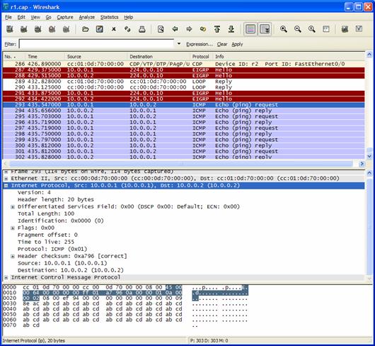
To begin capturing traffic at r1’s f0/0 interface and to write it to the file “r1.cap”, enter the following in the Dynagen Management window:
capture r1 f0/0 r1.cap
To view the traffic in real-time, open the file with Wireshark.:
The capture is continuing to write packets to the output file. If we ping r2 from r1, then hit the “reload this capture file” icon we see:
To stop capturing packets, enter:
no capture r1 f0/0
Dynamips / Dynagen can capture packets at serial interfaces too. In this case we must also specify the encapsulation we are using on our routers, so Wireshark will know how to decode the packets. Our encapsulation options are FR (Frame-Relay), HDLC, or PPP. To capture some traffic on our HDLC encapluated r2 to r3 link use:
capture r2 s1/0 r2.cap HDLC
Now we can open r2.cap, and the decode looks like this:
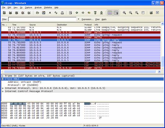
Now end the capture with “no capture r2 s1/0”. Note that you can have multiple captures running simultaneously against different interfaces on different routers.
Other Commands / Features
Dynamips and Dynagen provide more options and interface types than shown in this tutorial. Take a look at the “all_config_options.txt” file for list of all these options. For example, specifying an Ethernet adapter such as “e1/0” installs a PA-8E, “p1/0” installs a PA-POS-OC3, etc.
Here are some additional commands that can be used in the Dynagen management console that are not explained in this tutorial. Refer to the online help (command /? or help command) for usage:
- import / export – Imports and exports router configs from nvram to text files on your host. Can be used to get a copy of your current configs, or as a “snapshotting” feature to save your router configs before you make changes.
- push / save – Much like import and export, but the configs are stored as base64 encoded “blobs” right in your network file (specified with the “configuration” option). This allows you to distribute an entire lab with the network topology and IOS configs all in a single .net file
- filter – Applies a connection filter to an interface. Currently the only filter supported by dynamips is “freq_drop”, which drops x out of every y packets across a link (simulating intermittent packet loss).
- send – Used to send raw hypervisor commands to dynamips (see README.hypervisor included with the dynamips source for documentation on hypervisor commands). These hypervisor commands are how Dynagen communicates with Dynamips. This command would typically only be used uf developing new features in dynamips, experimenting, or simply curious.
- ver – outputs the version of Dynagen being used, as well as the versions of each dynamips instance Dynagen is connected to.
- hist – Dynagen management console command history (like “history” in bash)
- py – execute arbitrary python commands within the current dynagen namespace (for example, try “py print namespace.devices”)
- shell (or !) – pass commands to the DOS or Unix shell (e.g. “! dir” or “! ls”)